ELECTRICAL POWER SYSTEM PRESENTATION OF AIRBUS
There are two identical engine driven generators called Integrated Drive
Generators (IDGs). They are used as the main power source to supply
the A/C electrical network.
The IDG basically contains, in a common housing, a generator and a
Constant Speed Drive (CSD). The CSD gives a constant input speed to
the generator, which is required for a constant output frequency.
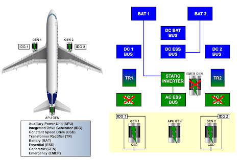
Each generator supplies 115V 400Hz AC to its own bus:
- generator 1 supplies AC bus 1,
- generator 2 supplies AC bus 2.
This supply is known as split operation, which means that the AC power
sources are never connected in parallel.
Each AC bus supplies a Transformer Rectifier (TR):
- AC bus 1 supplies TR 1,
- AC bus 2 supplies TR 2.
The TRs convert 115V AC into 28V DC to supply their associated DC
buses, DC 1 and DC 2.
DC bus 1 then supplies the DC BAT bus.
The DC battery bus can charge the batteries or receive power from the
batteries as a backup supply, if no other power sources are available.
The electrical system also includes two ESSential (ESS) Buses. One is
the AC ESS bus fed by AC bus 1 and the other is the DC ESS bus fed
by DC bus 1. These buses are used to supply the most critical A/C
systems.
This is the basic electrical system. We will now introduce some other
components, which also supply the system.
The entire electrical network can also be supplied by the APU generator.
On the ground, the aircraft electrical network can be supplied by an
external power source.
Any one of the power sources can supply the entire electrical network.
As no parallel connection is allowed on this A/C (split operation), we
have to give priorities to the different power sources in supplying the bus
bars.
AC 1 and AC 2 buses are supplied in priority by their own side generator,
then the external power, then the APU generator and then by the opposite
generator.

ABNORMAL CONFIGURATION
The electrical system has an ESS TR, which supplies the DC ESS
Bus in abnormal or emergency configuration.
In abnormal configuration (loss of TR1 or TR2) the ESS TR is
supplied by the AC ESS Bus.

EMERGENCY CONFIGURATION
In the event of emergency operation, the Emergency Generator (EMER
GEN) supplies the A/C with electrical power. The EMER GEN needs
hydraulic power to operate. This hydraulic power to drive the EMER
GEN is supplied by the Blue Hydraulic system via the Ram Air
Turbine (RAT). The RAT is located in the belly fairing and extends
automatically when AC BUS 1 and 2 have no voltage supply.
Then, the EMER GEN supplies the DC ESS BUS directly through
the ESS TR. In emergency configuration (loss of AC BUS 1 and AC
BUS 2) the EMER GEN supplies the ESS TR.

BATTERY ONLY CONFIGURATION
In emergency configuration with emergency generator not available,
BAT 1 supplies the AC ESS BUS via the static inverter and BAT 2
supplies the DC ESS BUS.
CONTROL AND INDICATING/PANEL LOCATION
The ELEC panel is installed on the overhead panel.
For emergency cases, there is an EMER ELEC PWR panel on the LH
side of the overhead panel.

MAIN PANEL/ECAM PAGE
The ECAM Electric System page shows all relevant data with regard
to the entire A/C Electrical Power Generation and Distribution
systems. The System page shown here is a normal configuration with
main generators supplying the network.
The battery voltage can be monitored either on the overhead panel or
the ECAM page. Each battery is controlled by a P/B Switch (SW).
Their related P/B SW control both main generators and the APU
generator.
A P/B SW also controls the external power.
The AC ESS FEED P/B SW lets the pilots change the supply to the
AC ESS bus from AC bus 1 to AC bus 2.
When the BUS TIE P/B SW is in the AUTO position, it lets the
opening or closing of the bus tie contactors in order to supply the AC
1 and AC 2 buses according to the power supply priorities.
When OFF, both bus tie contactors open to isolate one side of the
network from the other (e.g.: smoke configuration).
In case of failure, the IDG P/B switches disconnect the IDG from the
engine gearbox.
The GALY & CAB P/B SW lets galleys and some sub-buses be
manually shed.
The COMMERCIAL P/B SW is used for the shedding of all
commercial loads including the GALY & CAB related buses.

EMERGENCY PANEL
The EMER GEN TEST P/B is used on ground to test the EMERgency
GENerator or the Static Inverter.
In avionics smoke condition, the GEN 1 LINE P/B disconnects the
generator 1 from the busbar but the generator remains excited to supply
some fuel pumps.
When AC BUS 1 and 2 are no longer supplied, the RAT will extend
automatically to pressurize the blue hydraulic system, which powers
the EMER GEN, if the A/C speed is sufficient.
WARNING: ACTIVATION OF THE RED GUARDED MAN ON
PUSHBUTTON ON THE GROUND OR IN FLIGHT
WILL EXTEND THE RAM AIR TURBINE (RAT),
EVEN ON COLD AIRCRAFT.

COMPONENT LOCATION
The AC generators supply a 115 VAC, 3-phase, 400 Hz AC supply. The
IDGs and the APU have a nominal 90 kVA power whereas the EMER
GEN has a 5 kVA output.
The static inverter converts the direct current from battery 1 into an AC
current if no other source is available.
The Battery Charge Limiters (BCLs) control the battery coupling and
uncoupling to the DC BATTERY BUS to ensure battery charging and
protection. Each battery is rated at 24 V with a capacity of 23 Ah. All
TRs are identical and interchangeable.
In the Enhanced Electrical Power Generation System (EPGS), the GAPCU
controls the APU GEN and the external power. The Generator Control
Units (GCUs) protect and control the A/C network and generators. GCUs
and GAPCU supply AC electrical power parameters to show them on
the ECAM display. The main C/B panels are located in the cockpit.
The ESS TR is identical to TR 1 and TR 2. It converts 115 VAC to 28
VDC at a rate of 200 A. The EMER GCU connects the EMER GEN to
the ESS network, if all conditions are met.
The Ground Power Control Panel and the external power receptacle are
installed in front of the nose landing gear. On this panel, 2 Lights indicate
the Ground Power Unit availability (AVAIL light) and connection to the
A/C network (NOT IN USE light). The Ground Power Unit should supply
400 Hz 3 phase 115 VAC rated at 90 kVA minimum.
The MAINTenance BUS SW, located on the forward cabin Circuit
Breaker (C/B) panel, lets the AC and DC service buses be supplied
without energizing the whole A/C electrical network.
The aft cabin C/B panel contains only C/Bs.


MAINTENANCE/TEST FACILITIES
The GAPCU is the interface between the GCUs and the Centralized Fault
Display Interface Unit (CFDIU) for test purposes and fault reporting on
the MCDUs. Both the BCLs and the EMER GCU communicate with the
CFDIU for the same purposes. The TRs are connected to the CFDIU so
that they can be reset via the MCDU.

SAFETY PRECAUTIONS
When you do any maintenance task on the electrical system, make sure
that no AC or DC power source is connected to the aircraft electrical
circuits.
Before De-energizing aircraft electrics or before doing the Static Inverter
test, tell all personnel on the aircraft that the lights will go out.
Some components are heavy. You must make sure that you can hold the
component before its removal/installation. If it falls, it can cause injury
to personnel and damage to the equipment.
Dangerous arcing can occur if external power (GPU or Gate power) is
energized when trying to connect power to the aircraft. Make sure that
external power source is de-energized before connecting.
Components can remain hot for one hour following engine shutdown.
Be careful as hot parts and hot oil can cause injury and burn your eyes
and skin. Use protective clothing, as oil products are poisonous.
ENVIRONMENTAL PRECAUTIONS
Turn-off unused ground service equipment (GPU, Air conditioning
cart, etc...) if no work is being done or nobody is present on the
aircraft.

SAFETY PRECAUTIONS - ENVIRONMENTAL PRECAUTIONS


)
0 Comments