LANDING GEAR SYSTEM COMPONENT LOCATION OF A320
EXTENSION/RETRACTION SYSTEM
Landing Gear Control and Interface Units (LGCIU) 1 and 2 electrically
control the gear and door sequencing.
Each LGCIU in turn controls a complete gear cycle: one UP selection
and one DOWN selection.
The LGCIU in control is the active unit and the other is the standby
unit. The active unit changes after each retract/extend cycle (when
the L/G control lever is moved away from the DOWN position). If a
failure occurs in the active LGCIU, the standby LGCIU becomes
active.
Duplicated sensors monitor the gear up and down positions, the door
closed and open positions and the shock absorber compressed (ground
signal) and fully extended (flight signal) positions.
An interlock mechanism prevents unsafe retraction by locking the
lever in the DOWN position when any shock absorber is compressed.
The two systems are electrically segregated with different connections
on the related selector valves.
In case of failure, the gear can be mechanically extended from the
cockpit by means of a gravity extension crank handle.
After free fall extension, the L/G doors stay open and the L/G is locked
down by the lockstays and springs.
The normal extension and retraction control is available when the
free-fall handle-assembly is put back to its initial position.

NORMAL BRAKING
Normal braking is obtained when:
- The green hydraulic pressure is available,
- The Anti/SKID and Nose/Wheel Steering control switch is in the
ON position,
- The Parking Brake control switch is in the OFF position.
Electrical control is obtained:
- Through the pedals,
- Automatically on the ground by the auto brake system,
- In flight when the gear control lever is set to UP (in flight braking).
ALTERNATE BRAKING
The alternate brake system is powered by the yellow hydraulic system
and backed up by a brake accumulator.
The Alternate Braking Control Unit (ABCU) electrically controls the
alternate braking. The ABCU becomes active when the normal brake
system is faulty and/or low hydraulic pressure is detected in the green
system. Braking inputs are given by the brake pedals and transmitted
through the Alternate Brake Pedal Transmitter Unit to the ABCU,
which will control the braking pressure.
Wheel rotating speed from the tachometer, aircraft speed data and
braking pressure are supplied for A/Skid computation. The braking
pressure is read on the triple indicator.
The A/SKID regulation is disconnected, either electrically by setting
the A/Skid & N/W Steering switch to the OFF position, BSCU failure
or hydraulic low pressure (brakes being supplied by the brake
accumulator only). The pilot must refer to the triple pressure indicator
to limit brake pressure in order to avoid locking a wheel.
With the accumulator pressure only, a maximum of 7 full brake pedal
applications can be done. Nevertheless in that case the brake pressure
is limited to max. 1000 PSI by the ABCU.
PARKING BRAKE
The yellow hydraulic system or the brake accumulators supply brake
pressure.
Putting ON the parking brake, deactivates the other braking modes
and the A/SKID system.

NOSE WHEEL STEERING
The steering system uses the yellow hydraulic system to operate a
steering actuating cylinder, which changes the direction of the NLG
wheels.
The steering system receives hydraulic pressure in the following
conditions:
- A/SKID & N/W STeeRinG switch is in ON position,
- towing control lever is in normal position,
- at least one ENG MASTER switch is ON,
- aircraft is on ground.
The steering system is controlled by the BSCU, which receives order
from:
- the steering hand wheels (orders added algebraically),
- the rudder pedals,
- the autopilot.
When the rudder pedal disconnect pushbutton is pressed in, N/WS is
disconnected from the pedals.
The BSCU transforms the orders into N/WS angle. That angle has the
following limits:
- Ruder pedals: max 6 degrees,
- Hand wheels: max 74 degrees.
The NLG is equipped with Rotary Variable Differential Transducers
(RVDTs), which are used as feedback sensors to the BSCU.

SYSTEM OVERVIEW (continued)
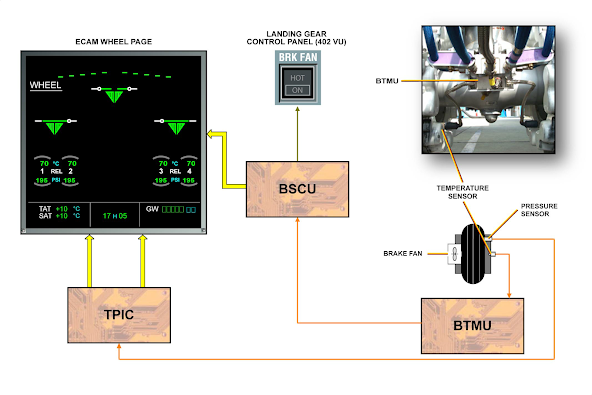
BTMU
One Brake Temperature Monitoring Unit (BTMU) per gear transmits
the brake temperature from the temperature sensors (one per brake)
to the BSCU.
FAN
The brake cooling system is a manually controlled system that
decreases the temperature of the brakes when they are too hot.
This optional system allows the brakes to be cooled in a short time
period.
One brake fan system with one BRK FAN HOT P/BSW is installed.
TPIS
The Tire Pressure Indicating System (TPIS) includes an electronic
sensor on each wheel and a Tire Pressure Indicating Computer (TPIC).
The TPIC controls and monitors the operation of the system and sends
data to other interfaced systems.
As an MPD item, the tire pressure can be checked through:
- a pressure gage (tool),
- or the ECAM WHEEL page.
COMPONENT LOCATION
The L/G computers are installed in the forward avionics bay.
Note that the Tire Pressure Indication Unit (TPIU) is an option.


0 Comments