POWER PLANT SYSTEM LINE MAINTENANCE IAE V2500 ENGINE
SYSTEM OVERVIEW
The IAE V2500-A5 engine is a two spool, axial flow, high bypass ratio
turbo fan power engine. The V2500-A5 powers the complete single aisle
family of aircraft except the A318. V2500-A5 engines are available in
several thrust ratings.
All the engines are basically the same. A programming plug on the
Electronic Engine Control (EEC) changes the available thrust.
The power plant installation includes the engine, the engine inlet, the
exhaust, the fan cowls and the reverser assemblies. The pylon connects
the engine to the wing structure. The engine is attached to the pylon by
FWD and AFT mounts.

THRUST REVERSER SYSTEM
Reverse thrust is controlled by the EEC. Reverse is manually selected
by the flight crew by lifting the latching levers on the throttle control
levers. The reverse thrust command is sent to the EEC and the EIU.
The DEPLOY command from the EEC is routed through the
INHIBITION RELAY (controlled by the EIU) as a second level of
protection against inadvertent deployment.
According to commands from the EEC and the EIU, a Hydraulic
Control Unit (HCU) supplies hydraulic power to operate the thrust
reverser. The thrust reverser assembly has 2 hydraulically actuated
translating sleeves. The translating sleeves are each powered by 2
actuators. As the translating sleeve moves aft during deployment, it
raises blocker doors to redirect the engine fan airflow.

ENGINE OIL SERVICING
CAUTION: Caution: The engine should be shut down for at least 5
minutes prior to oil servicing. This allows the residual
pressure in the oil tank to decrease. If you open the filler
cap when there is pressure in the tank the hot oil can spray
out and burn you.
NOTE: Note: If possible, the engine oil should be checked and serviced
within 5 to 60 minutes after shutdown.
Note: If the engine has been shutdown more 1 hour but less
than 10 hours, start the engine and run at idle for 3 minutes
prior to servicing.
Note: If the engine has been shut down for 10 hours or more,
you must dry crank the engine followed by an engine start and
idle run of at least 3 minutes duration. This is to ensure that the
oil level shown in the tank is correct before oil is added.
- open engine oil service door on left fan cowl,
- check oil level on the sight gage on the oil tank,
- raise filler cap handle to vertical (unlocked position),
- turn the oil filler cap to remove,
- add oil as necessary up to the FULL mark on the sight gage,
- install oil filler cap - make sure to LOCK the cap.
NOTE: Note: It is also possible to Pressure Fill the engine oil. Two
ports are installed on the oil tank, one for pressure and one for
overflow. See AMM for procedure.

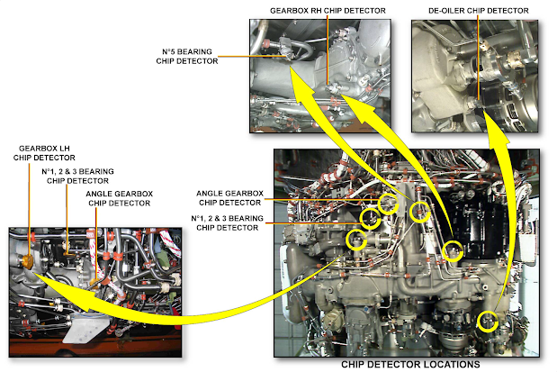
MASTER CHIP DETECTOR CHECK
The Master Magnetic Chip Detector (MCD) is located on the oil scavenge
filter housing attached to the oil tank. The probe will collect any magnetic
particles in the oil system. To check for contamination, remove the Master
MCD first:
- open rear access door at left fan cowl,
- push in and turn the MCD plug counterclockwise,
- check the AMM for examples of NORMAL and ABNORMAL
contamination
NOTE: Note: NO CONTAMINATION on Master MCD - No
maintenance required.
Note: CONTAMINATION on Master MCD - Inspect ALL
other MCD's.
- clean the MCD,
- replace seal ring and re-install - check that the RED marks are aligned

ADDITIONAL CHIP DETECTORS
Additional magnetic chip detectors are installed in the oil system to
isolate the source of metallic debris.
MEL / DEACTIVATION
FUEL FILTER CLOGGING
In case of a failure of the FUEL CLOG warning on ECAM, the aircraft
may be dispatched per MEL as long as the fuel filter is changed once
each day. The filter housing is part of the fuel cooled oil cooler on
the fan case LH side. Procedure:
- FADEC GND PWR selected OFF,
- open LH fan cowl,
- drain residual fuel using drain plug,
- open filter cover to remove and replace fuel filter element and
o-rings,
- close filter cover. Check AMM for correct torque value for filter
cover bolts,
- perform minimum idle check for leaks,
- close fan cowl.

T/R DEACTIVATION AND LOCKOUT
Per the MEL, one or both Thrust Reversers may be deactivated in the
STOWED position for dispatch. The deactivation procedure has two
parts. First, the Hydraulic Control Unit (HCU) is deactivated. Moving
the deactivation lever to the inhibit position prevents the pressurizing
valve from supplying hydraulic pressure to the reverser actuators. In
the second part of the deactivation procedure each translating sleeve
is secured (bolted) to the reverser structure preventing any movement.

START VALVE MANUAL OPERATION
In case of an electrical failure of the start valve, the valve may be
operated manually to start the engine. The aircraft may be dispatched
per the MEL with the valve INOP closed.
NOTE: Note: Do not operate the valve unless the starter system is
pressurized. Damage to the valve can occur.
- open the start valve access door on the RH cowl,
- establish communications with the cockpit (Interphone jack on engine
inlet cowl),
- on command from the cockpit, Use a 3/8" square drive to move the
start valve manual handle to the OPEN position.
NOTE: Note: Make sure you maintain pressure against the spring
tension to keep the valve open.
- after engine start, on command from the cockpit, move start valve
manual handle to CLOSED. Make sure that the start valve is fully
closed.

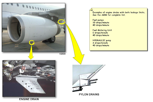
MAINTENANCE TIPS
The engine and pylon drain system is designed to collect fuel, oil, water
and hydraulic fluid from engine systems and accessories and discharge
them overboard through the engine drain mast and the pylon drain tubes.
For troubleshooting and leak isolation the drain mast body has separate
drains identified and visible with the cowls closed. The pylon drain tubes
collect fluids from individual pylon chambers, also for leak isolation.
If fluid leaks are found during transit operations, run the engine at idle
for 5 minutes. If the leak stops, the aircraft may be dispatched without
maintenance action. If leaks continue after 5 minutes, consult the AMM
(ATA 71-70) for maximum permitted leakage limits for all of the drains.
There are 2 limits for each drain. If the first limit is exceeded, the aircraft
may be dispatched and can continue to operate for a maximum of 25
hours or 10 flights as long as the second limit is not exceeded.
Here are some examples of engine drains with both leakage limits. See
the AMM for complete list.
ENVIRONMENTAL PRECAUTIONS
Do not discharge products such as oil, fuel, solvent, lubricant either in
trash bins, soil or into the water network (drains, gutters, rain water, waste
water, etc...).
Sort waste fluids and use specific waste disposal containers.
Each product must be stored in an appropriate and specific cabinet or
room such as a fire-resistant and sealed cupboard.


0 Comments