POWERPLANT SYSTEM COMPONENT LOCATION
SYSTEM OVERVIEW
The CFM56-5B engine is a dual-rotor, variable stator, high-bypass-ratio
turbo-fan power plant. The CFM56-5B can power all aircraft types of
the Single Aisle family. CFM56-5B engines are available in several thrust
ratings.
All the engines have the same basic configuration. A programming plug
on the Electronic Control Unit (ECU) changes the available thrust.
The power plant installation includes the engine, the engine inlet, the
exhaust, the fan cowls and the reverser assemblies. The pylon connects
the engine to the wing structure. The engine is attached to the pylon by
forward and aft mounts.

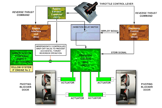
THRUST REVERSER SYSTEM
The reverse thrust is controlled by the ECU. A manual selection of
the reverse is done when the flight crew lifts the latching levers on
the throttle control levers. The reverse thrust command is sent to the
ECU and the Engine Interface Unit (EIU). The signal from the ECU
to the directional valve is supplied to an inhibition relay controlled
by the Engine Interface Unit (EIU) in relation to the position of the
throttle control lever.
In relation to commands from the ECU, a Hydraulic Control Unit
(HCU) supplies hydraulic power to operate the thrust reverser. The
thrust reverser uses 4 hydraulically operated pivoting blocker doors
to redirect the engine fan airflow.
COMPONENT LOCATION
The engine system components are at the following locations.
FADEC
The ECU is on the RH side of the fan case. The FADEC alternator is
on the gearbox.

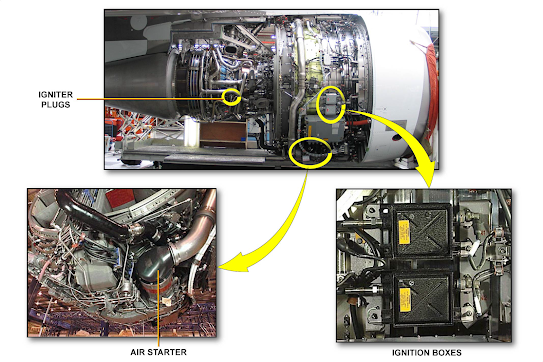
STARTING
Two ignition boxes are on the RH side of the engine core. The air
starter is on the RH side of the gearbox rear face.
FUEL
The primary components of the fuel system are installed on the LH
side of the fan compartment.
The fuel pump is operated by the gearbox. The Hydro-Mechanical
Unit (HMU) and the filter are installed with the pump.

AIR
The next picture shows the compressor airflow control system, the
turbine clearance control system and the transient bleed valve system.

OIL
The oil tank is on the LH side of the fan case.
The lubrication unit is operated by the gearbox.

THRUST REVERSER
The hydraulic shut-off valve is on the forward part of the pylon. The
HCU is installed on the forward part of the RH 'C' duct.


0 Comments